
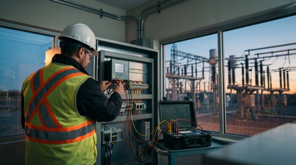
Relay protection in power systems keeps small faults from turning into big outages. Think of a protection relay as a smart sensor, because it watches current and voltage, spots something abnormal, and tells a circuit breaker to open. As a result, only the faulty section loses power, and the rest of the network keeps running.
However, a relay is only as good as its settings, its testing and the signals it receives. Therefore, anyone who works with substations, plant electrical systems or grid connections benefits from three ideas. These ideas are what a fault is, how engineers set a relay, and how they prove it works. Moreover, this guide explains all three in plain language. It also shows what the grid codes in Malaysia, Indonesia, Singapore and the Philippines say about protection, and where to find relay protection training.
Key takeaways
- Relay protection in power systems spots a fault and trips a breaker, so only the faulty section loses power.
- A good scheme balances five qualities, because it must act when needed, stay calm when not, isolate only the problem, act fast and notice small faults.
- Settings come from two studies, one on fault sizes and one on timing, so the network data behind them matters.
- Testing starts small and builds up: sensors and wiring first, then the relay, then the whole trip chain.
- Grid codes in Southeast Asia set expectations for protection, so always check the current edition.
Four numbers worth remembering
- 5 qualities that define a good protection scheme
- 20–30× the rated current that a protection CT must cope with during a fault
- 3 ms the transfer-time class that IEC 61850 sets for trip messages
- 0.3–0.4 s a conventional time gap between relays in series
Plain-English guide to relay protection in power systems
Key terms in everyday words
Fault: An unwanted connection that lets a large current flow, for example a wire touching earth.
Relay: The device that decides when to trip, because it reads the signals.
Circuit breaker: The heavy-duty switch that cuts the current once the relay decides to trip.
CT and VT: Sensors that shrink the network’s big currents and voltages, so the relay can read them as small signals.
Settings: The thresholds and time delays that tell a relay when to trip, so they define its behaviour.
Coordination: Arranging relays so the one nearest the fault trips first.
Secondary injection: Feeding test current and voltage straight into a relay, so engineers can check how it reacts.
Grid code: The rules for connecting to and running a national network, which also cover protection.
What is relay protection in power systems?
A protective relay is a device that trips a circuit breaker when it detects a fault, and it works in four quick steps. First, current transformers (CTs) and voltage transformers (VTs) shrink the network’s current and voltage into small signals. Next, the relay compares those signals with its settings, and then it sends a trip command if a signal crosses a setting. Finally, the breaker opens and isolates the problem, as Figure 1 shows.
Relay technology has also evolved. Older electromechanical relays work by magnetic attraction or induction. In contrast, modern numerical relays convert measurements to digital form and run software on a processor. As a result, one numerical relay can offer several protection functions and several sets of settings.
Five qualities of a good protection scheme
Engineers judge any protection scheme on five qualities, so Table 1 explains them in everyday terms.
- Dependability: The scheme acts when it must, so it removes a faulted element.
- Security: Outside faults and normal conditions do not cause a trip, because the scheme stays quiet.
- Selectivity: Only the faulty part trips, so as much of the network as possible stays in service.
- Speed: Fast clearing limits equipment damage and fault duration, so the scheme acts quickly.
- Sensitivity: The scheme notices abnormal conditions, even small ones, before they grow.
Dependability and security pull in opposite directions, so engineers balance them case by case rather than maximising one.
Zones of protection and back-up
Engineers split the network into protection zones. Each zone covers one item, such as a line, transformer, generator or busbar (the main connection point inside a substation), and has its own protection. Meanwhile, zones overlap so that no gap stays unprotected. If the primary relay or breaker fails, back-up protection steps in after a longer delay.
Fault basics: what do protection relays detect?
A fault is an abnormal connection that lets current flow where it should not, and faults fall into two groups. Symmetrical faults involve all three phases equally, while asymmetrical faults affect the phases unequally, as Table 2 and Figure 2 show for the four main types.
- Three-phase: All three phases connect together and the system stays balanced. These faults are rare, but they can badly damage equipment.
- Single line-to-ground: One phase touches earth, for example when a branch falls on one wire, which also makes this the most common type on lines.
- Line-to-line: Two phases touch each other, but they do not touch earth.
- Double line-to-ground: Two phases touch each other and also touch earth.
Because most line faults involve earth, relays dedicated to earth faults play a big role, and they commonly watch a signal called zero-sequence current.
Transient faults and auto-reclosing
Many faults on overhead lines are transient, which means they are brief. A tree branch, a bird or a lightning strike can cause a short circuit that clears once the breaker opens. For that reason, utilities commonly use auto-reclosing on overhead lines. The breaker closes again after a short delay to test whether the fault has cleared. If the fault remains, the breaker stays open until a crew repairs it. Underground cables differ, because their faults are typically persistent, so auto-reclosing is less common there.
Short-circuit studies
Because relay settings depend on fault size, engineers estimate how large a fault current could be with a short-circuit study. IEC 60909-0 also explains how to calculate it for balanced and unbalanced short circuits in low-voltage and high-voltage three-phase AC systems at 50 Hz or 60 Hz. Its third edition appeared in July 2026. Therefore, teams should confirm which edition their specification cites.
Which functions does relay protection in power systems provide?
Relays offer many functions, so IEEE device numbers give each one a standard label. IEEE C37.2-2022 assigns 95 function numbers and 22 acronyms, while Table 3 lists the numbers engineers meet most often.
- Instantaneous overcurrent (50): Trips right away, because current has risen above a set level.
- AC time overcurrent (51): Trips after a delay, so the wait depends on the current.
- Directional overcurrent (67): Adds fault direction, so overcurrent protection can tell forward faults from reverse ones.
- Distance (21): Estimates how far away the fault is, because it uses impedance.
- Differential (87): Compares the current entering and leaving a protected item, so it spots internal faults.
- Undervoltage and overvoltage (27 and 59): Spot voltage that is too low or too high, so they watch both extremes.
- Frequency (81): Spots frequency that drifts from normal, because the grid should stay near its nominal value.
- Auto-reclosing (79): Recloses the breaker after a brief fault.
- Breaker failure (50BF): Backs up the primary protection, because it acts when a breaker fails to open.
- Lock-out or master trip (86): Locks out the circuit after a trip.
Different equipment needs different functions. High-voltage lines form meshed networks, so engineers typically use distance or pilot relays on them. Transformers, in contrast, mostly rely on differential relays. Likewise, nearly every generator has stator protection (for the generator’s fixed winding), usually differential.
How do engineers set protection relays?
Relay settings follow a repeatable workflow, so Table 4 outlines the typical steps.
- Collect data: Gather the single-line diagram, equipment impedances, CT and VT ratios and existing settings, because the studies depend on them.
- Run a short-circuit study: Calculate fault currents for each fault type and location, so the settings can cover each case.
- Run a coordination study: Choose pickup values and time delays so relays operate in the right order.
- Compile and review settings: Check each setting against the study results before it goes into a relay.
- Apply and test: Load the settings into the relays and then test them.
- Document: Save the final settings and test records, because future changes and fault investigations need them.
Settings are only as good as the model behind them, so teams should keep the network data and the settings records current. Overall, relay protection in power systems stays reliable only when the studies, settings and records match the real network.
Overcurrent relay settings: how big, and how fast?
Overcurrent relays trip when current rises above a pickup level, and they then wait for a time that shrinks as the current grows. A time multiplier setting (TMS) moves the whole curve up or down, while IEC 60255-151 defines the standard curve shapes. Figure 3 plots three common ones, so read it from left to right: the bigger the fault current, the faster the trip.
The extremely inverse curve responds fastest as current rises, whereas the standard inverse curve responds slowest. Relay coordination also needs a time gap, called the coordination time interval, so the relay nearest the fault clears it first. A published technical paper, TSEWG TP-7, gives 0.3 to 0.4 seconds as a conventional margin. That margin also covers breaker opening time, relay overtravel (a mechanical overshoot) and a safety factor. Electronic multifunction relays have no overtravel, so teams can shorten the interval when tests show that the system still coordinates.
Distance and differential settings
Distance relays estimate how far away a fault is. They divide the voltage at the relay by the measured current to get impedance, then compare it with a reach setting. A typical first zone covers 80% of the line, so it stops short of the far end. A typical second zone covers 120%, so it reliably reaches past the far end. Third zones are sometimes switched off, whereas others cover the neighbouring line, as Figure 4 shows.
Transformer differential relays need extra care because switching a transformer on causes a short surge called inrush current. Inrush on a typical power transformer runs at 2 to 6 times full load, and a distinct signal called the second harmonic dominates it. Relays therefore use second-harmonic restraint, which blocks tripping when that signal is strong. The historical default threshold is 20%, while the adjustable range runs from 1% to 40%. If the threshold sits too high, the relay can trip as the transformer energises. By contrast, a threshold that sits too low can make the relay fail to trip for some internal faults.
These values are typical, not universal, so each utility and project sets its own criteria, and the owner’s requirements always come first.
Why do CTs and communications matter for protection?
A relay can only act on what it receives, so protection CTs must cope with fault currents of 20 to 30 times their rated current. If a CT’s core saturates, it distorts the signal, and the relay may see the wrong value. Too much burden (the load connected to the CT) also causes similar trouble, and long leads between the CT and the relay are a common cause. IEC 61869-2 covers CTs used with measuring instruments or protective devices, and it also replaced IEC 60044-1 and IEC 60044-6.
Digital substations add another layer, because relays talk to each other over Ethernet. IEC 61850 defines how substation devices communicate, while GOOSE messages carry trip and blocking signals between them. In the IEC 61850 performance classes, trip messages also carry a 3 ms transfer-time requirement.
How do teams approach protection relay testing?
IEEE C37.233-2023 describes how to test individual protection components and complete protection and control functions, and it uses a bottom-up approach. First, teams verify basic component behaviour. Then they test the connected pieces as working groups, and Table 6 follows the same logic with typical commissioning stages.
- CT, VT and wiring checks: Confirm the sensors and their wiring before any relay test.
- Output and circuit checks: Operate the relay outputs to check signalling and trip circuits, because both must work.
- Settings transfer: Load the approved settings into the relay once the wiring checks pass.
- Secondary injection: Feed in test current and voltage, so you can check pickup, timing and logic.
- Functional and trip tests: Simulate a fault, then confirm that the correct breaker trips.
- Load checks: Check measured values and phasor diagrams, because wiring errors, such as swapped phases, show up there.
- Documentation: Record the final settings and the test results, because they guide later work.
Secondary injection and safety
Teams rarely use primary injection (pushing real current through the primary equipment) because of its cost, so secondary injection does most of the work. A commissioning guide from Electrical Engineering Portal recommends three-phase test equipment, because modern devices monitor phase symmetry. Safety also needs attention at every stage. Never open a CT secondary circuit while primary current flows, because the CT can generate dangerous voltages. In digital substations, test sets also need GOOSE and Sampled Values capability.
Testing continues after commissioning, because relay protection in power systems must stay dependable for decades. Engineers also compare relay readings with load values and stored fault records between periodic tests, while our guide to electrical commissioning gives the wider commissioning picture.
Relay protection in power systems across Southeast Asia: what do grid codes say?
Grid codes set the rules for connecting to and operating a national network. Therefore, protection design for a new connection must follow the code of the market. Table 7 also summarises the codes that this article checked.
- Malaysia (Peninsular): Grid Code for Peninsular Malaysia, Main Code (KOD/ST/No.8/2025), Energy Commission. It is dated 28 March 2025 and effective 1 January 2026, while the Main Code also refers to the Connection Code for minimum technical, design and operational criteria.
- Indonesia: Aturan Jaringan Sistem Tenaga Listrik (Grid Code), Ministerial Regulation No 20 of 2020, Ministry of Energy and Mineral Resources. The ministry issued it on 30 December 2020, and it also adds rules for renewable energy plants and has five annexes, one for each power system.
- Singapore: Transmission Code, Energy Market Authority (listed under Codes of Practice). The version this article checked is dated 15 June 2026, and Section 6.3 also requires protection systems to be properly set and maintained in line with good utility practice, and to coordinate with the transmission system’s protection.
- Philippines: Philippine Grid Code, 2016 Edition, Energy Regulatory Commission. Chapter 7, Grid Protection, covers transmission protection schemes, line protection, redundancy and back-up, as well as grid-user protection arrangements.
Codes change, so teams should read the current edition before design work starts. In Singapore, for example, a connected party’s protection must coordinate with the transmission system’s protection. In addition, protection systems must meet the transmission licensee’s requirements and pass testing before energisation.
Protection work in the region spans utility substations, industrial plants and new generation or storage connections, so each project needs studies, settings and tests that match the market’s code. For network context, see our guide to power transmission systems in Indonesia.
What skills does relay protection in power systems require?
Protection work blends several disciplines, so teams typically need skills in:
- running short-circuit and coordination studies;
- configuring relay settings in numerical relays;
- selecting and testing CTs and VTs;
- commissioning and routine relay testing;
- working with IEC 61850 and digital substations;
- investigating faults using relay waveform and event records.
Training in relay protection in power systems can build these skills. Generator protection is a further specialism, so Electrical Generators, Excitation Systems and Governing Systems lists generator protective systems among its objectives.
Relay protection training: upcoming courses on the calendar
Relay protection training works best when it matches the job. For that reason, Relay Protection in Power Systems is an intermediate course that runs for two days (14 hours). It targets HV and MV systems from 11 kV to 330 kV. Its listed audience also includes:
- power protection and relay protection engineers;
- circuitry design engineers;
- project engineers and project managers;
- power network commissioning, planning and asset engineers;
- network field technicians.
The table below lists related courses currently scheduled on the EnergyEdge training calendar. Each course page shows the dates and venues on offer, so please check it for the latest details.
| Course | Dates |
|---|---|
| Switchgears and Transformers: Selection, Maintenance & Testing | 26–30 Oct 2026 |
| Electrical Power Failure Analysis and Investigation | 2–6 Nov 2026 |
| Commissioning of Electrical Equipment | 9–13 Nov 2026 |
| Planning, Design, Operation and Maintenance of Digital Substation | 22–26 Feb 2027 |
| Electrical Generators, Excitation Systems and Governing Systems | 1–5 Mar 2027 |
| Relay Protection in Power Systems | 28–29 Jun 2027 |
Build protection skills in your team
Explore the full course list, and also look at how in-house training can fit a team’s own network and standards.
© 2026 Asia Edge Pte Ltd & EnergyEdge Sdn Bhd. All rights reserved. EnergyEdge® is a registered trademark in Singapore, Malaysia and Indonesia.
FAQ
Relay protection is the use of protective relays to detect faults and abnormal conditions on a power network. When a relay sees a fault, it signals a circuit breaker to open. As a result, only the faulted section loses supply, while the rest of the network keeps running.
The relay detects the problem and decides to act. Then the circuit breaker opens the circuit and interrupts the fault current. Together, they work as a pair, because CTs and VTs supply the measurements.
Engineers choose a pickup current, a time curve and a time multiplier, based on a short-circuit study and a coordination study. In addition, they leave a time gap between relays in series, so the downstream relay clears the fault first.
Secondary injection means feeding test current and voltage directly into the relay’s inputs from a test set. As a result, the test checks pickup values, timing and logic without energising the primary equipment. Teams also use it far more often than primary injection.
A protection CT can face fault currents of 20 to 30 times its rating. If the core saturates, the secondary current becomes distorted, so the relay may see the wrong value. Therefore, engineers check CT ratio, burden and saturation behaviour during design and testing.
Common references include IEEE C37.2-2022 for device numbers, IEC 60255-151 for overcurrent relay requirements, IEC 61869-2 for current transformers, IEC 60909-0 for short-circuit calculations and IEEE C37.233-2023 for protection testing. However, the national grid code and the project specification also apply.
