
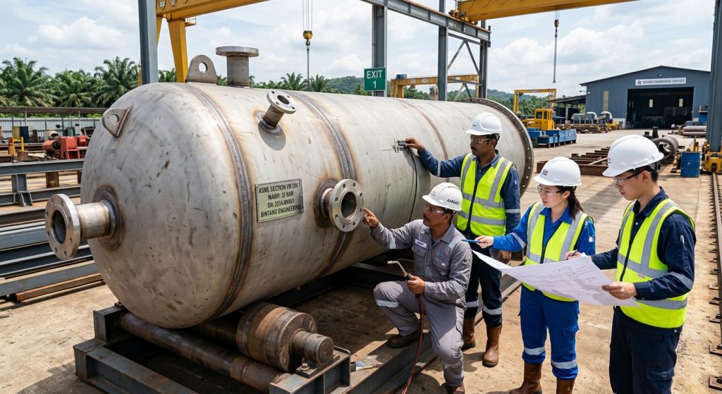
What is ASME BPVC Section VIII Division 1?
ASME BPVC Section VIII, Division 1 is the American Society of Mechanical Engineers’ construction code for unfired pressure vessels. It sets minimum requirements for design, materials, fabrication, examination, testing and certification of vessels operating above 15 psig. It is used by design engineers, fabricators, inspectors and owner-operators across oil and gas, petrochemical, power and process industries.
That is the short answer. The rest of this article explains what sits behind it: what the Code actually governs, how Division 1 differs from Division 2, the concepts that drive most of the engineering decisions, and — most usefully — the recurring mistakes that turn a straightforward vessel into a schedule problem.
Scope: When Section VIII Division 1 Applies
What counts as a “pressure vessel” in practical terms
A pressure vessel is a container designed to hold a gas or liquid at a pressure substantially different from ambient. In practice, that means anything from a small knock-out drum to a 60-tonne separator.
The working definition most engineers use on site is simpler: if the vessel holds pressure, is not fired, is not a piping component, and is not rotating machinery, Section VIII Division 1 is probably your construction code.
Division 1 generally applies to vessels operating at internal or external pressures above 15 psig (approximately 1 barg), with no upper pressure limit stated in the Code itself — though in commercial practice, vessels above roughly 3,000 psi are frequently taken to Division 2 or Division 3 for economic reasons.
Typical equipment governed by Division 1
- Two-phase and three-phase separators
- Knock-out drums, scrubbers and flash vessels
- Shell-and-tube heat exchanger shells and channels (in combination with TEMA)
- Reactors and contactors
- Air receivers and nitrogen storage vessels
- Amine and glycol contactors, surge drums, and reboiler shells
- Filter and coalescer housings
- Deaerators, accumulators, and pulsation dampeners
Typical industries
Upstream oil and gas production facilities, FPSOs and offshore platforms, gas processing plants, refineries, petrochemical complexes, LNG facilities, fertiliser and ammonia plants, power generation balance-of-plant, and increasingly hydrogen, CCUS and biofuel facilities.
What Division 1 does not cover
Division 1 excludes a defined set of equipment. Broadly, and without paraphrasing the Code’s own scope language, the exclusions cover categories such as:
- Vessels within the scope of other Code sections (fired boilers under Section I, nuclear components under Section III)
- Piping systems and their components, which fall under the ASME B31 series
- Fired process tubular heaters
- Pressure containers that are integral parts of rotating or reciprocating machinery
- Vessels below the pressure threshold, and certain small-diameter vessels
- Certain water and hot-water service vessels below defined limits
If you are working at the boundary — where a vessel nozzle becomes piping, or where a heater coil becomes a fired component — read the actual scope paragraphs rather than relying on rules of thumb. Boundary disputes between the vessel package and the piping package are one of the most common sources of late-stage RFIs on EPC projects.
Related training: The ASME BPVC Section VIII, Division 1 – Pressure Vessels Design and Construction course works through Code structure, scope and the most-used subsections and appendices with worked examples, which is exactly where boundary and applicability questions get resolved.
How Division 1 Is Organised
Understanding the structure of Division 1 saves an enormous amount of time, because the Code is not read front to back — it is navigated.
Subsection A — General Requirements. The “UG” paragraphs. These apply to all vessels regardless of material or fabrication method: design conditions, loadings, thickness formulas for shells and heads, openings and reinforcement, pressure relief, inspection, testing and marking.
Subsection B — Requirements by Method of Fabrication. UW for welded vessels, UF for forged, UB for brazed. Most process vessels are welded, so UW is where you will live: joint categories, joint types, joint efficiency, radiography requirements, and weld detail restrictions.
Subsection C — Requirements by Material Class. UCS for carbon and low alloy steels, UHA for high alloy steels, UNF for nonferrous, UCL for clad and lined, UHT for heat-treated ferritics, ULT for low temperature, ULW for layered, UCI and UCD for cast iron and ductile iron, UIG for impregnated graphite.
Mandatory Appendices. Supplementary rules that are part of the Code — flange design, ligament efficiency, NDE acceptance criteria for MT and PT, and more.
Nonmandatory Appendices. Good practice guidance — suggested design rules, installation and operation guidance, and similar.
A Division 1 calculation almost always requires you to read across all three subsections at once. A carbon steel welded separator, for example, draws thickness rules from UG, joint efficiency and radiography from UW, and impact test exemption rules from UCS. Missing one of the three is a recurring source of non-conformance.
Division 1 vs Division 2: The Comparison
This is the single most frequently asked question in pressure vessel engineering, and the answer is not “Division 2 is better.”
| Dimension | Division 1 | Division 2 |
| Design philosophy | Design by Rule. Prescriptive formulas and tables produce required thickness directly. | Design by Rule (Part 4) and Design by Analysis (Part 5), including elastic and elastic-plastic FEA methods. |
| Design margin philosophy | More conservative margin on tensile strength, which generally yields thicker sections for the same conditions. | Reduced margin on tensile strength, permitting thinner sections — but only because the analysis and quality requirements are more demanding. |
| Complexity of execution | Moderate. Can be executed with standard software or spreadsheets by an experienced designer. | High. Requires competent stress analysis capability, fatigue screening, and analyst judgement. |
| User’s Design Specification | Not mandated in the same formal, certified sense. | A certified User’s Design Specification is required and is a legal cornerstone of the design. |
| Manufacturer’s Design Report | Documentation required, but less formalised. | Certified Manufacturer’s Design Report required, prepared and certified by qualified engineers. |
| Materials | Broad range of permitted materials. | More restricted list, with tighter requirements on toughness and supplementary testing. |
| NDE intensity | Scaled to joint efficiency chosen; partial or no radiography is permitted with an efficiency penalty. | Substantially more extensive examination, with UT and volumetric requirements commonly mandatory. |
| Fabrication tolerances | Standard. | Tighter tolerances on forming, alignment and out-of-roundness. |
| Fatigue | Not routinely addressed; cyclic service must be handled by other means or by moving to Div 2. | Explicit fatigue screening and fatigue analysis rules. |
| Typical use cases | The vast majority of process vessels: separators, drums, exchangers, air receivers, moderate pressure and temperature duty. | High pressure, large diameter, thick wall, cyclic service, high value vessels where material savings justify engineering cost, or where the client or jurisdiction mandates it. |
| Cost profile | Lower engineering cost, higher material cost. | Higher engineering and QA cost, lower material cost. |
| Certification mark | U | U2 |
How to choose in practice
The decision is economic before it is technical. Division 2 pays for itself when the material and welding savings on a thick-walled or large vessel exceed the additional engineering, documentation and inspection cost. That crossover tends to sit at large diameters, high design pressures, or long production runs of identical vessels.
Division 2 also becomes the right answer, regardless of economics, when the service is cyclic enough that fatigue must be assessed formally, or when the owner’s specification or the jurisdiction requires it.
For most Southeast Asian process facilities — separators, drums, exchangers at moderate pressure — Division 1 remains the default and the correct choice.
Related training: The ASME VIII Pressure Vessels Design and Construction course covers design fundamentals, stress analysis, material selection, fabrication and testing across Section VIII, which gives engineers the basis to make the Div 1 / Div 2 call on commercial as well as technical grounds. For self-paced study, the ASME VIII – Design of Pressure Vessels for Industrial Plants e-learning course runs through Division 1 design conditions, joint efficiencies, shells, heads, nozzles and flanges over 120 hours of content.
A note on Division 3
Division 3 covers high pressure vessels, generally above 10,000 psi. It is a specialist area involving layered and autofrettaged construction, fracture mechanics based design, and is outside the scope of most process plant work.
Key Concepts Explained
Design pressure and design temperature
Design pressure is not operating pressure. It is the pressure used in the thickness calculation, set at or above the most severe coincident pressure the vessel will see, including relief device set pressure, static head, and credible upset conditions.
Design temperature is likewise the metal temperature expected under coincident conditions — not the fluid temperature at normal operation. It matters because allowable stress falls with temperature, sometimes sharply, and because material selection limits are temperature dependent.
Two further conditions must be defined and are frequently forgotten:
- MDMT (Minimum Design Metal Temperature): the lowest metal temperature at which the vessel may be pressurised. This drives impact testing requirements and is the primary defence against brittle fracture. Auto-refrigeration on depressurisation, ambient minima, and start-up conditions all feed into MDMT.
- External pressure / vacuum condition: vessels that will be steamed out, drained hot and sealed, or subjected to condensing vapour service can pull a vacuum. If vacuum is not in the design basis, the vessel is not designed for it.
Materials selection
Division 1 permits only materials listed in the Code, with allowable stresses taken from ASME Section II Part D. The selection question is not simply “is it permitted” but “is it right for this service.”
High-level considerations:
- Strength at temperature. Allowable stress at design temperature, not at ambient.
- Toughness at low temperature. Impact testing requirements, exemption curves, and the effect of thickness and PWHT on exemption.
- Corrosion and environmental cracking. Wet H2S service (HIC, SSC, SOHIC), chloride stress corrosion cracking in austenitic stainless steels, caustic and amine cracking, and the applicable industry standards such as NACE/ISO hardness and heat treatment requirements.
- High temperature degradation. Creep, graphitisation, temper embrittlement, high temperature hydrogen attack.
- Fabricability. Weldability, availability in the required thickness and form, and delivery lead time — a material that is technically correct but on a 40-week lead time is a schedule problem.
- Clad and overlay. Where corrosion resistance is needed but full solid alloy is uneconomic.
Joint efficiency and weld considerations
Joint efficiency is the factor applied to the allowable stress to account for the reduced reliability of a welded joint relative to base metal. It is not a material property. It is a function of the joint type, the joint category, and the amount of radiographic examination performed.
For a full penetration double-welded butt joint, the efficiency runs from full down to a lower value depending on whether the joint is fully radiographed, spot radiographed, or not radiographed at all. Each step down means more thickness.
The practical consequence: joint efficiency is a commercial decision made at design stage that binds the fabricator’s inspection scope. If the designer assumed full radiography to get thinner plate, and the purchase order did not price full radiography, someone is absorbing a cost.
Joint categories (A, B, C, D) define where on the vessel a joint sits — longitudinal seams, circumferential seams, flange-to-shell joints, and nozzle-to-shell joints. Category drives the permitted joint types and the examination requirements.
NDE overview: RT, UT, PT, MT
Non-destructive examination methods are defined in ASME Section V, while acceptance criteria for vessels are given in Section VIII.
| Method | What it finds | Typical application on vessels |
| RT (Radiographic Testing) | Volumetric defects — porosity, slag, incomplete penetration, cracks | Butt welds in shells and heads, primary means of establishing joint efficiency |
| UT (Ultrasonic Testing) | Volumetric and planar defects, thickness | Thick sections where RT is impractical, plate lamination checks, and as a permitted alternative to RT under defined conditions |
| PT (Liquid Penetrant Testing) | Surface-breaking defects in any material | Austenitic stainless and non-ferrous welds, nozzle welds, weld overlay |
| MT (Magnetic Particle Testing) | Surface and near-surface defects in ferromagnetic materials | Carbon steel fillet welds, nozzle attachment welds, back-gouged roots, post-PWHT surface checks |
| VT (Visual Testing) | Surface condition, profile, alignment, dimensional | Every weld, every stage — and the most under-valued method on most projects |
The important conceptual point: RT and UT are volumetric, PT and MT are surface. They are not substitutes for one another. An inspection plan that specifies “NDT as required” without stating method, extent, stage and acceptance standard is not an inspection plan.
Related training: For inspection-side professionals, the API 510 Pressure Vessel Inspectors Preparatory Course covers inspection of pressure vessels against their design codes, defect types arising during construction and operation, and detection through proper inspection and NDT. It is also available in a VILT format.
Nozzle reinforcement
Cutting a hole in a pressure boundary removes load-carrying metal. Reinforcement rules require that the metal removed be replaced by available metal within a defined zone around the opening — in the shell, the nozzle neck, the weld, and any reinforcing pad.
Two things go wrong routinely. First, the corroded condition is not checked: reinforcement adequate at nominal thickness may fail once corrosion allowance is deducted from every contributing element. Second, external nozzle loads from connected piping are applied without ever being communicated to the vessel designer.
Division 1 does not provide explicit rules for external nozzle loads. It requires the designer to consider all applicable loadings, but leaves the method open. In practice this is handled by WRC bulletins or FEA — and only if someone gives the vessel designer the piping load table before the vessel is fabricated.
Post weld heat treatment
PWHT relieves residual stress, improves toughness, and reduces hardness in the heat affected zone. It is required by thickness and material rules, and may additionally be required by service — for example, hardness-limited sour service.
PWHT has cascading consequences: it affects impact test exemption, it must be performed before certain final machining operations, it requires calibrated and charted furnace or local heating, and it consumes schedule. Discovering a PWHT requirement after fabrication has started is expensive.
Hydrotest vs pneumatic test
Every completed vessel must be pressure tested. The default is hydrostatic.
| Hydrostatic test | Pneumatic test | |
| Medium | Water (or other suitable liquid) | Air, nitrogen or other gas |
| Test pressure | Higher multiple of MAWP, adjusted for stress ratio at test temperature | Lower multiple of MAWP, adjusted for stress ratio |
| Stored energy | Low. A liquid-filled vessel that fails leaks or tears; it does not explode. | Very high. A gas-filled vessel failing at test pressure releases enormous energy. |
| Safety | Comparatively safe with normal precautions | Requires exclusion zones, remote monitoring, and a documented risk assessment |
| When used | Default for almost all vessels | Only when hydrotest is impractical — vessels that cannot tolerate water weight, internals or linings that cannot be wetted, or where traces of water cannot be tolerated in service |
| Key risks | Brittle fracture if metal temperature is too low; overpressure from thermal expansion; support and foundation overload from water weight; chloride contamination on stainless steel | Catastrophic energy release; requires staged pressurisation with holds and inspection |
| Practical cautions | Vent all high points; use a calibrated gauge with test pressure in the middle of its range; control test water chlorides for austenitic materials; verify metal temperature against MDMT plus margin | Never use as a convenience substitute; requires additional NDE of welds before test in most specifications |
The most common hydrotest failure mode is not the vessel — it is the paperwork. Test gauge out of calibration, metal temperature not recorded, hold time not logged, or the inspection performed at full test pressure rather than at the reduced examination pressure required.
Common Design Pitfalls
Each pitfall below follows the same structure: the symptom you will observe, why it happens, and how to prevent it.
1. Design conditions set on the wrong basis
Symptom. The vessel is fabricated and then found to be inadequate for relief valve set pressure, upset temperature, or a vacuum condition nobody designed for. In the worst cases this surfaces during commissioning.
Why it happens. Design pressure is copied from the process datasheet’s operating pressure with an arbitrary margin, without checking the relief device set point, static head from liquid contents, pump shut-off head, or credible upset scenarios. Vacuum is omitted because nobody thought about steam-out or condensing service. MDMT is set to ambient minimum without considering auto-refrigeration on blowdown.
How to prevent it. Make the design basis a formally reviewed document, not a line on a datasheet. Require sign-off from process, mechanical and operations before it is issued to the vessel designer. Explicitly state, for every vessel: design pressure, design temperature, MDMT and its basis, full vacuum yes/no, corrosion allowance, and all coincident load cases. If any field is blank, the design basis is not complete.
2. Material selection mismatched to service
Symptom. Cracking, hydrogen blistering, or accelerated corrosion within months of start-up, in a vessel that fully satisfied the Code.
Why it happens. The Code confirms a material is permitted at a given pressure and temperature. It does not confirm the material is suitable for the process fluid. Sour service, chlorides, amine, caustic and hydrogen services each impose requirements — hardness limits, PWHT, HIC-tested plate, material restrictions — that come from industry standards outside Section VIII.
How to prevent it. Run a materials selection review separately from the Code calculation, with a corrosion or materials engineer, before the material requisition is placed. Document the process environment in the design basis, including trace contaminants. Where sour service applies, state the applicable standard and its supplementary requirements in the purchase specification — not as a general reference, but as specific testing and hardness clauses.
3. Joint efficiency assumed, examination not procured
Symptom. The fabricator’s quotation does not include full radiography; the design calculation assumed it; the vessel is now under-thickness for the examination actually performed.
Why it happens. Design and procurement operate on separate documents. The designer picks a joint efficiency to optimise thickness. The requisition specifies “NDT to code” without stating the radiographic extent. The fabricator prices the minimum defensible interpretation.
How to prevent it. State the required examination extent explicitly on the vessel datasheet and in the purchase requisition, in the same words the calculation assumed — full radiography, spot radiography, or none — and cross-check it during technical bid evaluation. Make the joint efficiency assumption a visible line item on the calculation summary sheet, not buried in software output.
4. Corrosion allowance applied inconsistently
Symptom. Shell thickness includes corrosion allowance; nozzle necks, reinforcing pads, internal supports and flange faces do not. Reinforcement calculations pass in the new condition and fail in the corroded condition.
Why it happens. The corrosion allowance is entered once in the software and assumed to propagate. Internals, clad interfaces and bolted joints are handled by different people or different models.
How to prevent it. Require corroded-condition checks as a mandatory output of the design calculation, including nozzle reinforcement, flange rating, and external pressure. Define explicitly whether internals, clad layers and non-pressure-retaining attachments carry corrosion allowance, and state it in the design basis rather than leaving it to convention.
5. External nozzle loads never communicated
Symptom. The piping stress analysis, completed after the vessel is on order, produces nozzle loads that exceed anything the vessel designer considered. Either the piping is redesigned late, or the nozzle is reinforced by field modification.
Why it happens. Vessel design and piping stress analysis sit on different schedules and often with different contractors. Nobody owns the interface.
How to prevent it. Issue allowable nozzle load tables with the vessel datasheet at enquiry stage, based on standard load envelopes, and require the piping designer to work within them or raise a deviation. Make the nozzle load table a named deliverable with a named owner, not an assumed exchange.
6. Under-specifying NDE requirements
Symptom. Disputes during fabrication about which welds get examined, by what method, at what stage, and against which acceptance criteria. Every dispute is a variation order.
Why it happens. The specification says “NDE in accordance with ASME VIII Div 1.” That sentence is true and almost useless, because the Code offers options and the fabricator will select the cheapest permitted one.
How to prevent it. Specify method, extent, timing and acceptance standard for each weld category. Where the owner requires more than the Code minimum — and most owners do — say so explicitly and price it. Include NDE after PWHT and after any repair, since these are frequently omitted.
7. Documentation and traceability gaps
Symptom. At handover, material test reports cannot be matched to heat numbers on the as-built drawing. The manufacturer’s data report cannot be signed without a concession.
Why it happens. Heat number transfer during plate cutting is a manual process. Substitutions are made on the shop floor when a plate is short. Records are compiled at the end of fabrication rather than as it proceeds.
How to prevent it. Audit material traceability early — at the first plate cutting stage, not at final documentation review. Require a material substitution procedure that mandates engineering approval before use, not after. Build the manufacturing record book progressively and review it at each hold point, so the final compilation is a check rather than a reconstruction.
8. Miscommunication between design, fabrication and inspection
Symptom. As-built deviations discovered at final inspection. Repairs performed and then queried. Drawings that no longer match the vessel.
Why it happens. Three organisations, three document sets, and an RFI process that runs slower than the fabrication sequence. Fabricators make sensible shop-floor decisions that were never fed back to the designer.
How to prevent it. Hold a formal pre-inspection meeting before fabrication starts, with the designer, fabricator, owner’s inspector and Authorized Inspector in the same room, working through the ITP line by line. Set a maximum RFI turnaround time contractually. Require that any deviation from approved drawings is raised as a concession before the work is done, and make that a stated condition of acceptance rather than a preference.
Common Inspection Pitfalls
1. An incomplete inspection and test plan
Symptom. Fabrication progresses past a stage the owner intended to witness. The activity is either accepted on documentation alone or partially undone.
Why it happens. The ITP is written generically, copied from a previous project, or issued after fabrication starts. Stages are listed without clear designation of who does what.
How to prevent it. Build the ITP around the actual fabrication sequence for that vessel, not a template. For every line, state the activity, the reference procedure, the acceptance criteria, the record generated, and the intervention level for each party — manufacturer, owner, third party and Authorized Inspector. Issue it approved before the first material is cut.
2. Missing or ill-defined hold points
Symptom. A hold point is passed because the notification was late, or because it was never clear whether it was a hold or a witness.
Why it happens. Hold, witness, surveillance and review points are used interchangeably. Notification periods are not agreed. The owner’s inspector is covering multiple shops.
How to prevent it. Define the intervention levels in writing at the pre-inspection meeting, including the consequence of passing a hold point without release. Agree notification periods realistically — an inspector who needs a flight cannot respond to 24 hours’ notice. Keep hold points few and meaningful; an ITP with fifty hold points will be ignored, an ITP with eight will be respected.
3. Misinterpreting acceptance criteria
Symptom. An indication is rejected by one party and accepted by another. Rework is performed that was never required, or a genuine defect is accepted.
Why it happens. The examination method comes from one Code section and the acceptance criteria from another. Personnel apply criteria they know from a different code — piping, structural, or a previous employer’s standard — rather than the one that governs this vessel. Owner specifications sometimes impose criteria stricter than Code without saying so clearly.
How to prevent it. State the governing acceptance criteria explicitly for each NDE line on the ITP, by document and paragraph. Where the owner’s specification is stricter than the Code, say so in the same line. Require that NDE reports cite the acceptance standard applied. Resolve interpretation disputes through a named technical authority, agreed in advance, rather than at the point of dispute.
4. NDE personnel qualification gaps
Symptom. Completed examination records are challenged at the documentation review because the technician’s certification does not cover the method or the material, or the written practice is missing.
Why it happens. Subcontracted NDE is engaged on price, and certification is checked at the end rather than the start. The employer’s written practice, which governs qualification, is not requested.
How to prevent it. Verify the NDE contractor’s written practice and each technician’s certification before any examination is performed, and record that verification in the manufacturing record book. Check that the certification covers the specific method, level and material group in use. Where interpretation is involved, confirm the certifying level is authorised to interpret, not merely to perform.
5. Calibration and measurement traceability issues
Symptom. Every reading taken with an instrument is invalidated because the calibration certificate expired, is missing, or cannot be traced to a national standard.
Why it happens. Calibration is treated as an administrative box rather than a technical requirement. Site instruments are shared and undocumented. Pressure gauges are selected on availability rather than range.
How to prevent it. Require calibration certificates for every measuring device before use — pressure gauges, thickness meters, hardness testers, temperature recorders, and reference blocks — with traceability to a recognised national standard and an expiry date beyond the planned use. For pressure testing specifically, confirm the gauge range places the test pressure near mid-scale, and require a second gauge or recorder as a check. Log instrument serial numbers in the test record, not just the fact that a gauge was used.
6. Pressure test execution and record failures
Symptom. The test is completed and then repeated, because the record is incomplete or a condition was not controlled.
Why it happens. Metal temperature is not measured, only ambient. Hold times are estimated. Inspection is carried out at full test pressure instead of the reduced examination pressure. Chloride content of test water is not verified for stainless steel vessels. Vessel supports and foundations are not checked for the water weight.
How to prevent it. Use a pressure test procedure with a completion record that captures metal temperature, gauge identification and calibration status, pressurisation steps, hold times, examination pressure, water quality where applicable, and the disposition. Verify the supporting structure is designed for the flooded weight before filling. Confirm venting at all high points before pressurising.
7. Late engagement of the Authorized Inspector
Symptom. The Authorized Inspector raises fundamental questions about design documentation or the quality system after fabrication is substantially complete.
Why it happens. The AI is treated as a final certifier rather than a participant throughout construction.
How to prevent it. Involve the AI from design review and the pre-inspection meeting onward. The AI’s acceptance of the design documentation, the quality control system, and the fabrication sequence is what makes the data report signable — and it is far cheaper to obtain that acceptance progressively than retroactively.
Related training: For teams managing repairs and alterations on existing pressure equipment, the ASME PCC-2 Repair of Pressure Equipment and Piping e-learning course covers repair methodologies and acceptance criteria for in-service equipment.
Practical Checklist: Design → Fabrication → Inspection → Handover
Use this as a project gate checklist. Anything unchecked is an open risk, not an oversight to be caught later.
Stage 1 — Design basis (before design starts)
- [ ] Design pressure defined, with basis stated (relief set point, static head, pump shut-off)
- [ ] Design temperature defined, coincident with design pressure
- [ ] MDMT defined, with the governing scenario stated
- [ ] Vacuum / external pressure condition stated explicitly, yes or no
- [ ] Corrosion allowance defined, and its application to internals and nozzles stated
- [ ] Process fluid composition documented, including trace contaminants
- [ ] Sour service, chloride, amine, caustic or hydrogen service assessed and standards named
- [ ] All applicable loadings identified: weight, wind, seismic, transport, lifting, nozzle loads
- [ ] Cyclic service screened — Division 1 or Division 2 decision documented
- [ ] Governing Code edition and addenda stated
- [ ] Jurisdictional and statutory requirements identified
- [ ] Owner specification deviations from Code identified and priced
Stage 2 — Design and documentation
- [ ] Thickness calculations complete for all pressure parts, new and corroded condition
- [ ] Joint efficiency assumption stated on the calculation summary and matched to the specified NDE extent
- [ ] Nozzle reinforcement checked in the corroded condition
- [ ] Allowable nozzle load table issued to piping
- [ ] External pressure calculation completed where vacuum applies
- [ ] Impact test requirements or exemptions determined and documented
- [ ] PWHT requirements determined, from both thickness and service
- [ ] Flange design and rating verified at design and test conditions
- [ ] Support, saddle or skirt design completed for all load cases including hydrotest
- [ ] Drawings reviewed and approved by owner before fabrication release
Stage 3 — Pre-fabrication
- [ ] Pre-inspection meeting held with designer, fabricator, owner inspector and Authorized Inspector
- [ ] ITP approved, with intervention levels and notification periods agreed
- [ ] WPS and PQR reviewed and approved for all joints
- [ ] Welder qualifications verified and current
- [ ] NDE contractor written practice and technician certifications verified
- [ ] Material test reports received and reviewed against the specification
- [ ] Positive material identification plan agreed where alloys are involved
- [ ] Material substitution procedure agreed, requiring pre-approval
Stage 4 — Fabrication and examination
- [ ] Heat number traceability audited at first cutting
- [ ] Forming and dimensional tolerances verified
- [ ] Fit-up inspected before welding at designated stages
- [ ] NDE performed to the specified method, extent and stage
- [ ] NDE reports cite the acceptance standard applied
- [ ] Repairs performed to approved procedure, re-examined, and recorded
- [ ] PWHT charts reviewed against the approved procedure
- [ ] NDE after PWHT completed where required
- [ ] Hardness testing completed where service requires it
- [ ] Hold points notified and released in writing
Stage 5 — Pressure test
- [ ] Test procedure approved before test
- [ ] Supporting structure and foundation verified for flooded weight
- [ ] Test medium quality verified, including chlorides for austenitic materials
- [ ] Metal temperature measured and confirmed against MDMT with margin
- [ ] Test gauge calibrated, in range, with certificate on file
- [ ] All high points vented before pressurisation
- [ ] Pressurisation in stages, with hold times recorded
- [ ] Examination performed at the correct reduced pressure
- [ ] Test record completed and signed by all parties, including the Authorized Inspector
Stage 6 — Handover
[ ] Documentation transferred to the owner’s integrity management system
[ ] Nameplate details verified against the data report
[ ] Manufacturer’s Data Report completed and signed
[ ] As-built drawings issued, reflecting all approved deviations
[ ] Manufacturing record book complete: MTRs, WPS/PQR, welder logs, NDE reports, PWHT charts, dimensional records, test records, concessions
[ ] Relief device sizing and set pressure confirmed against the final design pressure
[ ] Preservation and shipping requirements met
[ ] Baseline thickness readings taken for future in-service inspection
Where to Take This Next
Reading the Code is necessary but not sufficient. Most of the failures described above are not failures of Code knowledge — they are failures at the interfaces between design, procurement, fabrication and inspection, where the Code is silent and project discipline has to fill the gap.
PetroEdge Asia and EnergyEdge run structured training across the pressure equipment lifecycle:
- ASME BPVC Section VIII, Division 1 – Pressure Vessels Design and Construction — Code structure and organisation, design and construction requirements, materials, fabrication, inspection, testing and certification, with emphasis on applying Design by Rules to real engineering scenarios.
- ASME VIII Pressure Vessels Design and Construction — design fundamentals, stress analysis, material selection, fabrication techniques, welding considerations and testing, delivered through lectures, calculation workshops and code interpretation exercises.
- ASME VIII – Design of Pressure Vessels for Industrial Plants (E-Learning) — 120 hours of self-paced Division 1 content covering design conditions, loading, joint efficiency, shells and heads under internal and external pressure, nozzles and flanges.
- API 510 Pressure Vessel Inspectors – Preparatory Course — in-service inspection against ASME Section VIII and API 510, defect types, integrity management, and preparation for API certification. Also available as VILT.
- ASME B31.3 Process Piping Systems in Industrial Plants — the piping side of the vessel–piping boundary, essential for engineers working the interface.
- ASME PCC-2 – Repair of Pressure Equipment and Piping (E-Learning) — repair methods and criteria for in-service pressure equipment.
- Practical Application of ASME BPVC Section I for Oil & Gas EPC Project Engineers — for teams working on fired boiler scope and its interfaces with Sections II, V and IX.
- EN 13445 – Design and Fabrication of Pressure Vessels (E-Learning) — the European framework, for projects with PED compliance and CE marking requirements.
Browse the full oil and gas technical training portfolio or contact the team for an in-house proposal tailored to your project and team size.
This article is a general technical explainer and is not a substitute for the Code itself. Always work from the current edition and addenda of ASME BPVC Section VIII, Division 1, together with the applicable jurisdictional requirements and owner specifications for your project.
Frequently Asked Questions
ASME BPVC Section VIII is the part of the ASME Boiler and Pressure Vessel Code that governs the construction of pressure vessels. It is divided into three divisions covering different pressure ranges and design approaches: Division 1 for general pressure vessel construction, Division 2 for alternative rules including design by analysis, and Division 3 for high pressure vessels.
Division 1 is the general, most widely used division of Section VIII. It provides prescriptive “design by rule” requirements for the design, materials, fabrication, examination, testing and certification of pressure vessels operating above 15 psig. Vessels built to Division 1 and certified carry the ASME U certification mark.
Division 2 is more stringent in engineering, documentation and examination requirements. It demands a certified User’s Design Specification, a certified Manufacturer’s Design Report, more extensive non-destructive examination, tighter fabrication tolerances and, where applicable, formal fatigue analysis. In exchange for that rigour, Division 2 permits a lower design margin, which generally results in thinner walls for the same conditions. Division 1 is less demanding to execute but produces heavier vessels. Neither is “safer” — both are designed to be safe. They distribute the effort differently: Division 1 spends material, Division 2 spends engineering.
A pressure vessel is a container that holds pressurised fluid, designed for containment and often for a process function such as separation or storage. Piping is a conveyance system that transports fluid between equipment. They are governed by different codes: pressure vessels by ASME BPVC Section VIII, and process piping by the ASME B31 series, most commonly B31.3 for process plants. The boundary between them is normally defined at the vessel nozzle — typically at the first circumferential joint, flange face or weld end — and that boundary must be stated explicitly in the project documents, because responsibility for design, examination and testing changes at that point.
A hydrostatic test pressurises the completed vessel with water above its maximum allowable working pressure, to demonstrate structural integrity and leak-tightness before the vessel enters service. It is required because it is a direct, whole-vessel proof of the design, materials, fabrication and welding together — something no calculation or spot examination can provide. Water is used rather than gas because a liquid stores very little energy under pressure, so a failure during test leaks or tears rather than exploding.
The four most common are radiographic testing (RT) and ultrasonic testing (UT) for volumetric examination of welds, and liquid penetrant testing (PT) and magnetic particle testing (MT) for surface examination. Visual testing (VT) applies throughout. The examination methods themselves are defined in ASME BPVC Section V; the acceptance criteria for vessels are given in Section VIII. RT is particularly significant in Division 1 because the extent of radiography directly determines the permitted joint efficiency, and therefore the required wall thickness.
No. Section VIII is a construction code — it governs new vessels up to the point of certification. Once a vessel is in service, inspection, repair, rerating and fitness-for-service assessment fall under standards such as API 510 for pressure vessel inspection, API 579 for fitness-for-service, and ASME PCC-2 for repair methods.
At minimum: the design basis and datasheet, the design calculations, approved fabrication drawings, material test reports with traceability, welding procedure specifications and procedure qualification records, welder qualification records, the approved ITP, NDE procedures and reports, PWHT charts, dimensional inspection records, the pressure test record, any approved concessions, and the signed Manufacturer’s Data Report with nameplate details.
